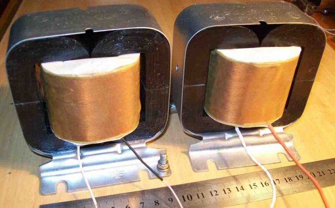
Transformator
In recent years, there has been some sort of mystic and mysteriousness, knowledge that is available only to the elected. It's part of it, but... Methodologies for the engineering calculation of transformers were developed more than half a century ago and there have been no significant changes in these years only in the use of new magnetic materials of higher quality [1]. The basic principles and ratios remained unchanged. The laws of physics don't change in half a year...
Calculation of output transformer parameters
The reference data for the calculation of the transformer shall be determined in the calculation of the end cascade of the force. They are the output power, the present load resistance in the auda chain, the primary wet induction and the induction of the transformator dispersion [2].
Determination of the required dimensions of the magnetic wire
Initially, the required dimensions of the magnetic wire must be determined. The suitability of available iron can be estimated in an indicative way:
where Vc is active steel;
L1 is the calculated induction of the primary wet, Mr.
UA is the voltage amplitude on primary wet clams, B;
FH is the lower border frequencies, Hz;
Bmax is the maximum magnetic induction amplitude, Gs.
S is the section area of the magnetic wire, cm2;
lC is the mean length of the magnetic power line, see.
For the armoured magnetic wire, the mean length of the magnetic power line shall be calculated as:
And for the bar:
where the symbols correspond to those accepted on Rice. 1.
Rhys. 1 Main dimensions of magnetic lines
When evaluating the dimensions of the magnetic conductor, the value of Vmax should be approximately 7,000 to 8,000 Gs for plastic and 10000 Gc for whale cuts of iron.


