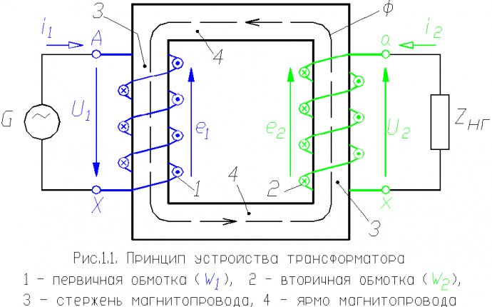
Transformator Principle
 In transformators and load-response-response-response-response-resistant transducers (PRDs) a circuit and contact system is used to switch the number of turns of wet without breaking the electrical circuit.
Pressure control in load transformers shall be performed on the side of the higher voltage within +-10 per cent of the rated voltage of eight steps at 2.5 per cent, i.e. within +-4x2, 5 per cent.
Under the RPN, the transition from one retread to another without breaking the current in the supply chain is possible through the application of the two parallel switching (P1 and P2) system, closed to the current-restricting reactor P, the mean point of which is included in the restructure. The reactor is a three-phase induction stack with a steel heart with a blind eye. It shall be placed inside the transformer ' s tank on the upper or lower assemblies of the fair.
In rice. 1 shows the principled design of the built-in RPN for 35 kV high voltage mods for one transformation phase. The 110 kV flowchart differs from the fact that the adjusting cables are not in the middle of the washing, but in neutral and the star form the interconnection of the three phases of reactors.
Rhys. 1. Ring contact: a - working position, b is the intermediate position, 1 is the contact ring, 2 is the spiral rib, 3 is the spring axis, 4 is the knee joint, 5 is the contact rod
It should be noted that the built-in stress management of the vehicle transformers is carried out in the middle of the wet rather than by neutral.
In rice. 2 shows the switching sequence of one response (with A6 contact A7) without rupture of the feeding network.
Transformator RPN
At first, contact K2 is washed, and then the R2 switched to contact A7. Contact K2 is then re-engineered, resulting in the switching section, through contacts A6 and A7, now being closed. To limit the current in this section, the reactor R is used. The contactor K1 of the upper parallel branch is then washed and the deteriorated switch P1 is also transferred to contact A7. The contact K1 shall then be activated and the process of switching one step shall end.
Three double switches P1 - P6 are placed inside the transformer tank because they work without current. Contacts K1 to K6 shall be placed in a separate tank with oil reinforced on the side wall of the transformer tank. Each group of three switches and contactors shall be operated at the same time by one common vault. The switch shall be carried out simultaneously on three phases.
The necessary sequence of the contactor and switches shall be achieved by the installation of the fistula.


