Working Principle Of The Current Transformer
 Electricity accounting
The current transformers (TT) are intended to convert the primary network to a secondary, standard level 1 or 5 A used as a signal in measurement, accounting and relay protection systems.
In order to obtain reliable information on the primary network mode and the primary current I1, such transformers have a special design compared to power or voltage transforms.
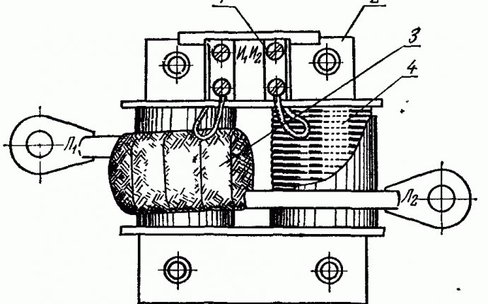
Working principle♪ The main constituent parts of the TT are the magnetic conductor, primary and secondary circuits. All values relating to the primary chain of TT are indexed by figure 1, for secondary - 2.
The primary wet shall be included in the controlled network in series, so it shall have little resistance so that the voltage falls near. The secondary moor shall be placed on measuring or other small resistance instruments, so the operating mode of TT shall be considered close to the short circuit.
I1, passing through the ω1 wilt turns, creates a variable magnetic flow F1 in the magnetic wire. Under its influence, F1 is recharged with I2, which in turn creates a flow of F2 directed at F1.
 The flux flux F0 represents the difference between the primary and secondary flow and is used to moisture the heart. If the flow of F0 is emitted by the luminous flux of F0, we shall receive an expression describing the principle of TT work:
; F;_0=F_1-F_2; (1) ; I;_0 ω_1=I_1 ω_1-I_2 ω_2; (2)
I_1 ω_1, I_2 ω_2. The difference between these values depends on the sum of the current I0. In large terms, expression 2 characterizes error. current transformer♪ The value of the secondary current given TT is as follows:
I _2^'=I_1∙Z_0/(Z_0+Z_2^'+Z_n^') (3)
where Z0 is the resistance of the vagina; Z2 is the resistance of secondary circuit wires; Zn is the combined resistance of the devices in the secondary circuit; I1 is the primary current.


